
Factory Layout: Plan Utilities Before You Place Machines
Material piping, cooling water, vacuum and power routes are decided once. Why utility planning must happen before machine placement, and what it costs after.

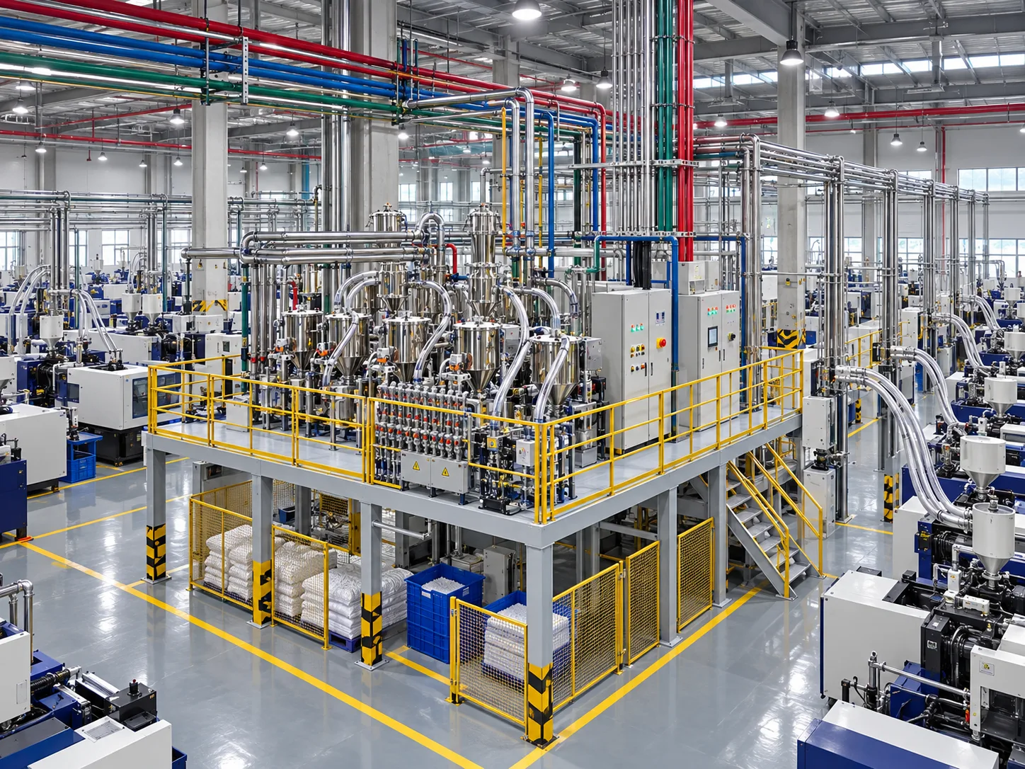
Most molding halls are laid out machine-first: presses are positioned, then utilities are routed around them. That sequence guarantees longer pipe runs, more bends, harder maintenance access and a hall that cannot easily add machines later.
Utility-first planning costs the same in materials and much less in everything else. The reason it is skipped is simply that machine delivery dates feel more urgent than pipe routes.
What should be planned before machines are placed?
Five systems, all of which interact:
| System | What it needs | Cost if added later |
|---|---|---|
| Material piping | routes from storage to each machine | high — pipes cross machine rows |
| Cooling water | supply and return headers, sized for total load | high — headers need machine access |
| Chilled water | separate loop from tower water | medium |
| Vacuum / compressed air | main ring with drops | medium |
| Power and control | busbar or cable tray routes | high — tray routing is layout-dependent |
Why does machine-first layout cost more?
Three mechanisms:
- Longer runs — utilities routed around machines rather than through planned corridors are typically 20–40 % longer, which adds both material and pressure drop.
- More bends — every avoided bend reduces vacuum loss, water pressure drop and the chance of material settling in a pipe.
- No maintenance access — valves and filters placed behind a machine are never serviced, and unserviced filters are a leading cause of conveying problems.
What does a workable layout look like?
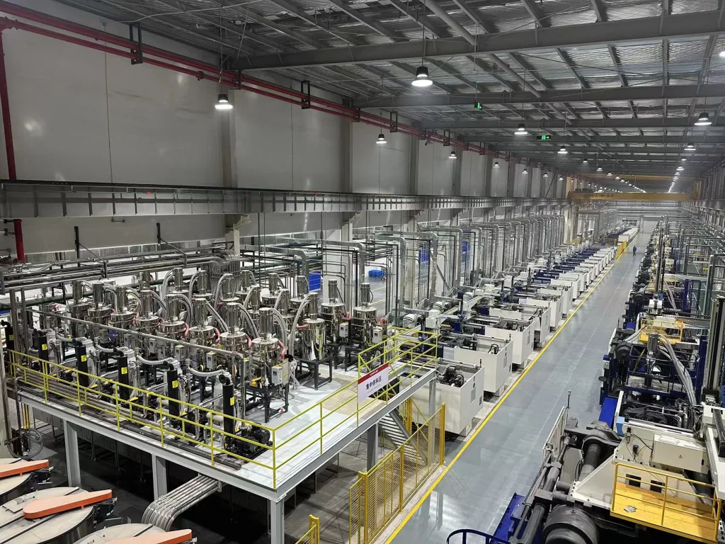
The pattern that works in most halls is a spine-and-branch arrangement: a main utility corridor down the centre or along one wall, with short branches to machine rows. Material storage and drying sit at one end of the spine, and chilled water headers run parallel to it rather than across it.
Two rules make the spine work: keep the main corridor clear of machines permanently, and put every valve and filter on the corridor side rather than the machine side.
How much space should utilities take?
As a working allowance, plan 8–12 % of the production floor for utility corridors, plus a dedicated material area of 30–80 m² for silos, dryers and conveying equipment depending on machine count. Plants that plan zero usually end up with pipes over walkways and a material area that grows into the production floor.
What about future capacity?
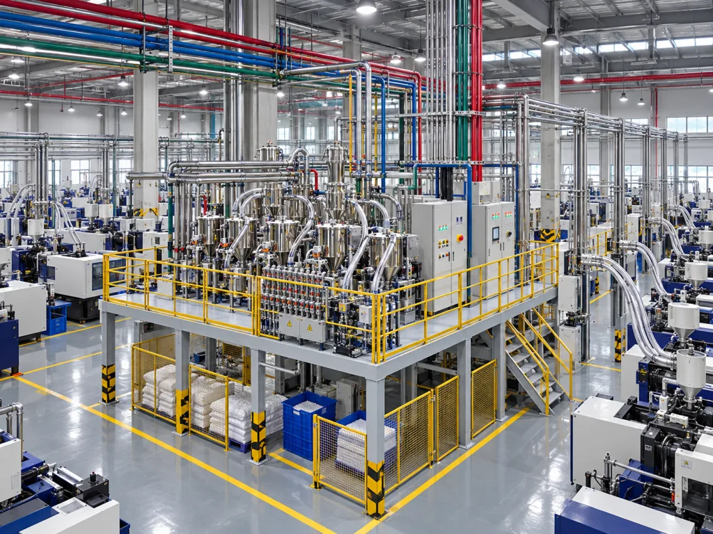
Design the spine for the machine count you expect in three to five years, not today’s. Pipe and header capacity is cheap to oversize at installation and expensive to add later, because adding capacity usually means shutting the hall down.
Where to go next
The material side of the layout is defined by the centralized feeding system, and the centralized feeding controller handles routing once the physical layout exists. Where utilities are being planned from scratch, our engineering team can produce the combined drawing before machine placement is fixed.
Send us your hall dimensions, machine list and expected growth and we will return a utility layout for review.